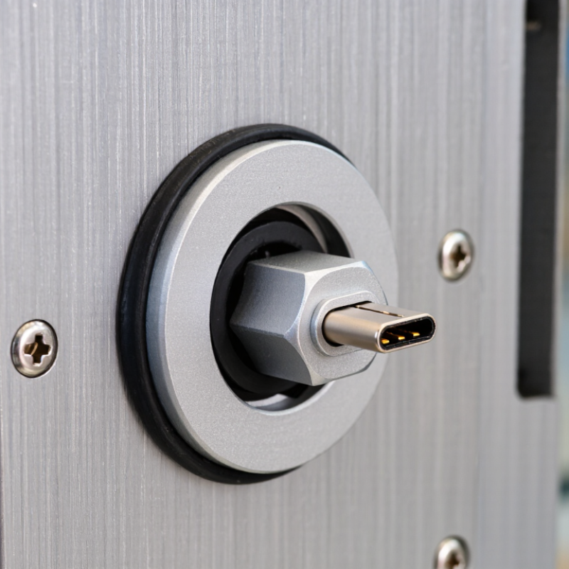
| What it is | A panel-mounted USB Type-C connection that brings a USB-C port through an enclosure wall. Many designs use a short internal cable or a pass-through coupler. | Enclosures, control panels, equipment cabinets, and other installations where a port needs to be accessible from outside. | Check whether the assembly is a passive pass-through or contains active electronics; this affects compatibility and performance. |
| Data capability | Supported speeds depend on the connector, internal cable, host, device, and protocol. USB 2.0 supports up to 480 Mbit/s; USB 3.2 Gen 1 supports up to 5 Gbit/s when the complete link supports it. | Peripheral connections, data access, and service ports on instruments or embedded equipment. | Select a connector and cable rated for the required data rate. Verify the assembled link in the intended configuration, especially for high-speed signals. |
| Power delivery | USB-C describes the connector shape, not a guaranteed power level. USB Power Delivery capability depends on the source, sink, cable, and connector assembly. | Charging or powering equipment through an enclosure-mounted port, where supported by the system. | Confirm voltage, current, and power ratings for every part of the path. Do not assume a bulkhead connector supports a particular USB PD profile. |
| Panel mounting | Mounting styles commonly include threaded bodies with a retaining nut or flange-mounted designs. Cutout size and permitted panel thickness vary by product. | Metal or plastic panels, instrument housings, and machine enclosures. | Use the connector’s specified cutout dimensions and panel-thickness range. Deburr the opening and leave clearance for the connector body, nut, cable, and mating plug. |
| Environmental protection | Ingress protection is model-specific and may depend on correct mounting, a suitable gasket, and whether the port is mated or capped. | Outdoor or dusty installations, washdown areas, and equipment exposed to moisture. | Check the stated IP rating and its test conditions. Fit seals as directed, protect unused ports as specified, and avoid overtightening that could damage the seal or panel. |
| Cable routing and strain relief | The internal lead and its bend limits affect reliability and signal performance. Some assemblies provide cable retention; others require separate support. | Portable equipment, frequently accessed service ports, and installations subject to vibration or movement. | Route the cable without sharp bends, pinching, or tension at the connector. Add strain relief where needed and keep the internal lead clear of moving or hot components. |
| Shielding and grounding | The connector shell and cable shield may provide an electrical path, but grounding behavior depends on the design of the connector and enclosure. | Industrial controls, measurement equipment, and systems where electromagnetic compatibility matters. | Follow the equipment’s grounding and shielding design. Verify shell-to-panel continuity where required and avoid creating unintended ground paths. |
| Final verification | A bulkhead connection can add another connector interface to the USB link, so compatibility should be assessed as part of the complete system. | All installations where reliable data transfer, charging, or environmental sealing is required. | After assembly, check mechanical retention, sealing, device recognition, data transfer, and power operation under the expected conditions. |
 English
  Česká republika
 Deutsch
 Dutch
Dutch Polska