What Is a Voltage Instrument Used For?
A Voltage Instrument does more than display a number. It helps technicians verify whether power supplies, batteries, control panels, and electronic circuits operate within expected limits. Touch the probes to a battery’s terminals, and the display reveals its potential difference. In a factory cabinet, the same basic task can help locate a failed supply or an unexpected voltage drop. The reading is useful. The context matters, too.
NIST’s Special Publication 330 explains the SI system behind electrical units, while NIST Technical Note 1297 provides guidance for expressing measurement uncertainty. These references underline a practical point: a precise-looking display is not automatically a trustworthy result. Probe placement, instrument range, calibration status, and electrical noise can all affect what appears on screen. Small details count.
Metrologist Dr. Stephan Schlamminger’s published work on quantum electrical standards highlights the importance of reliable, traceable measurements. A useful takeaway is simple: “Resolution is not the same as accuracy.” That sentence is an editorial summary, not a verbatim quotation. Readers should check the original source before attributing it directly. A capable Voltage Instrument may be a digital multimeter, voltmeter, or specialized tester, selected for the job and measurement conditions. This guide explains what these instruments measure, where they are used, and how to interpret their readings responsibly. Even a familiar tool deserves a second look.
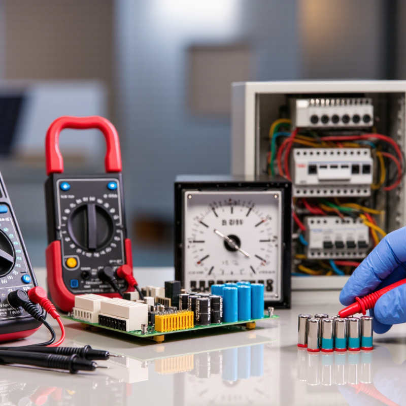
Voltage Instruments Measure Potential Difference in AC and DC Circuits
A voltage instrument measures potential difference between two points in an AC or DC circuit. In a DC circuit, such as a battery-powered sensor, it can show polarity and a steady voltage drop across a component. In AC circuits, it typically reports an RMS value, which helps technicians assess supply levels at outlets, motors, and control panels. A multimeter suits routine checks; an oscilloscope reveals waveform shape and brief fluctuations. Small differences matter.
Measurement also supports power-quality checks. IEC 61000-4-30:2015 describes methods for measuring voltage magnitude, dips, swells, and interruptions. The U.S. Energy Information Administration’s 2022 Annual Electric Power Industry Report records average customer interruptions lasting 5.6 hours, including major events, and 2.5 hours when those events are excluded. These figures describe outages, not voltage faults, but they show why technicians verify supply conditions after service returns.
A meter reading is not the whole story: probe placement, instrument range, and electrical noise can affect results. Readings should be compared with equipment specifications, and the instrument’s safety rating must match the circuit. I would also recheck an unexpected value before treating it as a fault.
How Voltmeters Work: A Typical Digital Meter Has 10 MΩ Input Impedance
A voltage instrument measures the electrical potential difference between two points. A typical digital meter has an input impedance of 10 MΩ, meaning it behaves like a very large resistance across the circuit being tested. Connect the probes in parallel, not in series. At 5 volts, a 10 MΩ input draws about 0.5 microamps. That small current usually lets the meter observe a circuit without changing it much.
Usually. In a sensitive, high-impedance circuit, even a little current can affect the reading. A sensor output may shift when the meter is connected, or a long wire may pick up stray electrical noise. The displayed value is useful, but it is not always the untouched value. I find that easy to overlook when a screen gives a crisp number. Input impedance can also vary by meter, measurement mode, and signal frequency, especially for AC readings. Check the instrument’s specifications when the circuit is delicate, and compare readings with the probes connected and removed if the result seems surprising. A 10 MΩ input is a helpful standard, not a guarantee of zero influence.
Main Instrument Types: Digital Multimeters, Oscilloscopes, and Voltage Probes
What Is a Voltage Instrument Used For?
A voltage instrument reveals electrical potential between two points, but each type answers a different question. A digital multimeter gives a stable reading, such as 12.1 volts across a battery or 230 volts at a socket. It suits checks on wiring, power supplies, and sensors. An oscilloscope shows voltage changing over time. Its trace can expose a brief startup dip that a multimeter’s slower display may miss. NIST’s voltage-metrology materials describe Josephson standards with relative uncertainty near 10⁻¹⁰. That is a reference-laboratory benchmark, not the accuracy of a handheld meter.
Voltage probes connect instruments to circuits and shape what can be measured safely and clearly. A standard probe works for many low-frequency signals; a differential probe measures between two points when neither is at ground potential. Probe capacitance can also load a circuit and alter a fast signal. Small effect, sometimes. Check the probe’s voltage and frequency ratings, attenuation setting, and the instrument’s input limits before testing. IEC 61010-2-030 sets safety requirements for measuring circuits, while NIST calibration guidance distinguishes instrument performance from traceable reference measurements. A clean screen is not proof of a sound measurement: loose ground clips, poor contact, and unexpected transients can all mislead.
What Is a Voltage Instrument Used For? - Main Instrument Types: Digital Multimeters, Oscilloscopes, and Voltage Probes | Instrument Type | Primary Purpose | What It Shows | Typical Uses | Key Strength | Important Consideration |
| Digital Multimeter (DMM) | Measures voltage, and commonly also current and resistance. | A numeric reading; many models can measure both DC and AC voltage. | Checking batteries, power supplies, circuit nodes, and electrical continuity. | Provides straightforward measurements that are easy to read and record. | Most DMMs show a measurement over time as a value rather than displaying the full waveform. |
| Oscilloscope | Displays how voltage changes over time. | A waveform, typically with voltage on the vertical axis and time on the horizontal axis. | Examining signal shape, timing, frequency, noise, transients, and circuit behavior. | Reveals changes and events that a single numeric reading may not show. | Correct probe setup, grounding, bandwidth, and voltage limits matter for accurate and safe measurements. |
| Voltage Probe | Connects a circuit test point to a measuring instrument, commonly an oscilloscope. | By itself, it generally does not display a reading; the connected instrument displays the signal. | Making contact with a circuit while transferring its voltage signal to an instrument. | Provides a practical interface for measuring signals at circuit points. | Probe attenuation, input impedance, bandwidth, voltage rating, and grounding can affect the measurement. A probe is typically an accessory, not a standalone meter. |
Choosing a Meter: Compare Range, Accuracy, and AC Bandwidth Ratings
What Is a Voltage Instrument Used For?
A voltage instrument measures electrical potential between two points, but choosing one requires more than checking its maximum voltage. Compare the working range, accuracy, and AC bandwidth with the signal you expect to measure. A 600 V range may safely include a 230 V reading, yet a lower range can show finer changes. Check the stated accuracy format, often written as a percentage of reading plus display counts.
For example, with 0.1 V resolution and accuracy of ±(0.5% of reading + 2 counts), a 230.0 V reading carries an approximate ±1.35 V instrument error. That is an illustration, not a universal specification. NIST Technical Note 1297 explains how measurement uncertainty should account for multiple uncertainty components.
Specifications can still mislead.
For AC measurements, check the frequency range over which the accuracy is guaranteed. A meter rated from 40 Hz to 500 Hz may suit ordinary 50 or 60 Hz checks, but not every distorted waveform or fast-changing signal. IEC 61000-4-7 addresses harmonic and interharmonic measurement up to 9 kHz; that scope does not mean a basic meter measures harmonics accurately. Look for bandwidth and waveform limitations in the instrument’s specification. A common mistake is treating “true RMS” as a substitute for adequate bandwidth. It is not. Match the meter to the signal, then leave margin for unexpected frequencies. On a noisy bench, that small detail matters.
Safe Measurement: IEC 61010 CAT III 600 V Ratings Cover Distribution-Level Tests
What Is a Voltage Instrument Used For?
Safe Measurement: IEC 61010 CAT III 600 V Ratings Cover Distribution-Level Tests
A voltage instrument measures electrical potential between two points. Technicians use it to check outlets, panels, breakers, and fixed wiring. For distribution-level work, a CAT III 600 V rating indicates suitability for specified measurements in that category, up to the instrument’s rated voltage. It also reflects testing against transient electrical stresses. A rating is not a promise of safety. The meter and leads must both carry appropriate ratings.
Tips: Inspect the case and leads for cracks. Confirm the range and connection points before testing. Keep fingers behind the probe guards. If a panel’s condition or circuit rating is unclear, stop and seek qualified guidance.
Details matter. CAT III describes the measurement environment, not permission to touch exposed conductors. The 600 V figure does not cover every setup; check whether the rating applies between terminals and to ground. Follow the instrument’s instructions, use suitable protective equipment, and verify operation on a known source before and after a test. It is easy to trust a printed label too much. Real circuits can be confusing, especially in crowded panels, so careful setup still matters.
What Is a Voltage Instrument Used For?
Voltage instruments measure electrical potential between two points, helping users check circuits, verify supply levels, and troubleshoot electrical systems.
Reading the chart: These are illustrative nominal AC system voltages; actual values vary by location and installation. A CAT III 600 V rating is for measurements on distribution-level fixed installations within the instrument’s specified limits. It does not mean every circuit below 600 V is safe to test—use appropriately rated leads and follow safe measurement procedures.
 English
 Česká republika
 Deutsch
 Dutch
 Polska