Top FLs Gate Valve Components and Their Functions
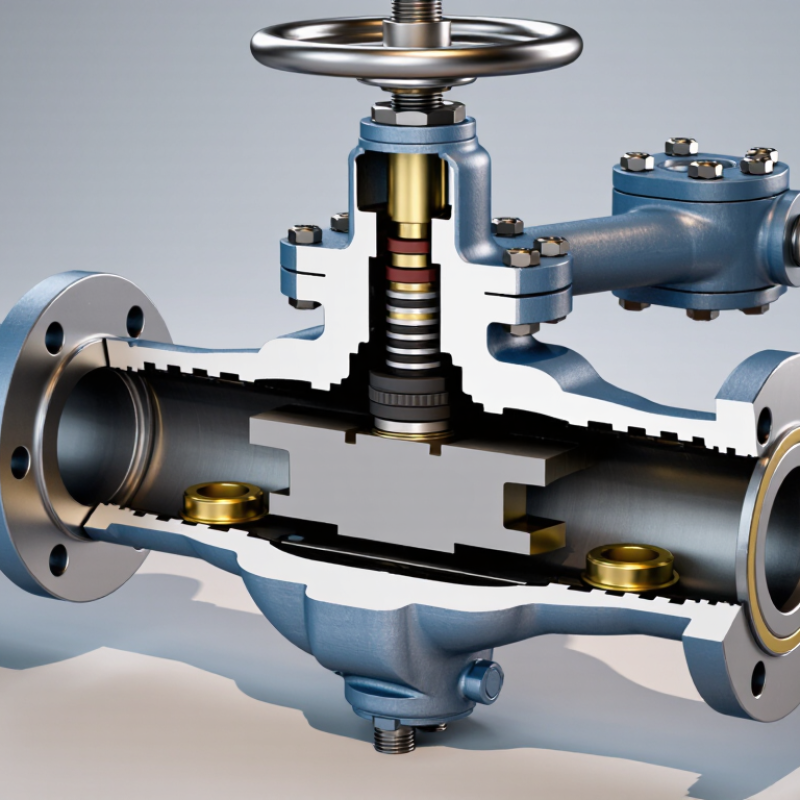
Fls Gate Valve Components work together to control flow, contain pressure, and support dependable operation in demanding service. Their roles are easiest to understand by looking closely at the parts that move, seal, and carry load. The body forms the pressure boundary. The gate travels through the flow path, while the seats create the sealing surfaces. The stem transfers motion from the handwheel or actuator. The bonnet closes the body, and packing helps limit leakage around the stem. Small details matter. A scored seat or worn packing can change how a valve performs.
This introduction follows the component-by-component structure of the article, explaining each part’s function and how it relates to the others. A useful expert quotation should be verified before publication; no source was provided for a named specialist or a direct quote. Use this placeholder: “[Verified expert name], [role or organization], says, ‘[Insert a checked quotation about gate valve components and their functions].’” That step matters. An invented attribution would weaken the article’s credibility.
Readers will find practical context alongside the component descriptions, including what to inspect and why fit, material condition, and assembly deserve attention. The explanation is not a substitute for manufacturer documentation. Valve designs differ, and even familiar parts can vary across models. The details are worth checking.
FLs Gate Valve Overview: API 6A Wellhead and Tree Equipment
Top FLs Gate Valve Components and Their Functions
FLs Gate Valve Overview: API 6A Wellhead and Tree Equipment
An FLs gate valve is used in API 6A wellhead and tree assemblies to isolate or control flow. Its body contains a gate that moves across the flow path, while seats seal against the gate when the valve closes. The stem transfers motion from a manual handwheel or actuator. In practice, even a small amount of debris on a seat can affect sealing. That detail matters.
API Spec 6A, Wellhead and Tree Equipment, defines rated working-pressure classes from 2,000 to 20,000 psi. It also sets requirements for product specification levels (PSL) and performance requirements (PR), which help buyers compare manufacturing controls and validation tests. Select the pressure class, material, and temperature rating for the actual well conditions—not just the connected piping. The valve’s bonnet, seals, and connections need compatible ratings too. A specification is useful, but it does not replace inspection. Check traceability records and test documentation before installation, and confirm that operating procedures match the valve configuration. Field conditions can be less tidy than drawings suggest.
Body and Bonnet: API 6A Working Pressure Ratings up to 20,000 psi
The body and bonnet form the pressure-containing envelope of a gate valve. Their job is direct: contain well pressure while supporting the gate, seats, and stem assembly. API Specification 6A and ISO 10423 list working-pressure classes up to 20,000 psi, including 5,000, 10,000, and 15,000 psi classes. These are equipment ratings, not predictions of the pressure a particular installation will experience. Details matter.
At the 20,000 psi class, material selection, wall design, bolting, seals, and manufacturing quality must work together. The bonnet joint is a critical interface; damaged sealing surfaces or incorrect assembly can undermine the pressure boundary. A rating applies only within the specified equipment configuration and service limits. It does not make every body-and-bonnet combination suitable for every fluid or temperature.
API 6A also defines validation and testing requirements, so buyers should check the documented class, material requirements, and test records for the exact valve. A heavy casting may look reassuring. Looks are not evidence. In practice, reviewing traceable inspection records can feel tedious, but skipping that step leaves an avoidable gap.
Gate and Seats: How Slab-Gate Designs Control and Seal Flow
In a slab-gate valve, the gate is a flat plate that slides across the flow path. When open, its bore aligns with the pipeline, leaving a near-straight passage. When closed, solid sections of the gate move between the seats and interrupt flow. Simple geometry, demanding fit.
Seats sit on either side of the gate and form the sealing interfaces. Depending on the design, they may be fixed or spring-loaded, with metal or soft sealing surfaces. Line pressure can help press a floating seat against the gate, but sealing behavior also depends on pressure direction, materials, and service conditions. In actual service, ideal contact is not always perfect; grit or wear can create a faint leak path. A clean-looking valve is not proof of a sound seal. That is easy to overlook.
Tips: Confirm the valve’s pressure and temperature ratings before operation. Keep the bore clear of weld spatter and debris during installation. Move the gate fully open or closed; partial positioning can accelerate wear. If operating force changes, investigate rather than forcing it.
Stem and Seals: Actuation and Pressure Containment Functions
In an FLs gate valve, the stem transfers force from a handwheel or actuator to the gate. Turning the stem moves the gate away from or into the flow path. In rising-stem designs, its visible travel can help show valve position; non-rising stems need another indicator. No guesswork. Stem threads and guides must move smoothly, since corrosion or debris can make operation stiff. A stiff stem is not always a seal problem, though it deserves inspection.
Stem packing surrounds the stem where it passes through the bonnet, helping contain process pressure while allowing movement. A gland follower applies pressure to the packing. Too little compression can allow leakage; too much can increase friction and wear. The bonnet gasket seals the joint between bonnet and body, adding another part of the pressure boundary. These seals have limits. Temperature, fluid compatibility, pressure, and installation condition all matter. During maintenance, look for dampness around the stem, damaged packing, or a loose gland. Adjustments should follow the valve’s service instructions, because tightening by feel alone can create problems. Seal performance is not always obvious from a clean exterior.
End Connections and Testing: API 6A PSL and Performance Requirements
End connections must match the wellhead configuration, pressure class, and service conditions—not just the nominal bore. API Specification 6A lists working-pressure ratings from 2,000 to 20,000 psi, including 3,000, 5,000, 10,000, and 15,000 psi. Its PSL levels run from PSL 1 to PSL 4, while PR1 and PR2 describe separate performance validation categories. Higher numbers do not replace correct material selection or sound installation.
For a flanged or hub connection, verify dimensions, seal condition, and pressure rating against the approved equipment records. API 6A testing requirements provide a framework for pressure and functional checks; test records should identify the unit, acceptance criteria, and calibrated instruments. PSL selection affects quality controls and documentation, so specify it before procurement. A polished certificate is useful, but it cannot reveal every handling mark on a sealing face.
Tips: Check the connection profile and seal before assembly. Record the test pressure, hold time, and result. Small documentation gaps are easy to overlook—and worth reviewing.
Top FLs Gate Valve Components and Their Functions - End Connections and Testing: API 6A PSL and Performance Requirements
| Category | Component or Requirement | Function or Purpose | Typical Verification or Consideration |
|---|---|---|---|
| Valve component | Body | Contains the pressure and provides the main flow passage and interfaces for internal parts. | Material, pressure rating, dimensions, and pressure-containing integrity are verified against the specified design and applicable API 6A edition. |
| Valve component | Bonnet | Closes the valve body and supports or encloses the stem and upper sealing arrangement. | Connection and sealing surfaces are inspected; the assembled pressure boundary is included in applicable pressure tests. |
| Valve component | Gate or slab | Moves across the flow path to open or close the valve. | Dimensions, surface condition, and interaction with the seats are checked to support reliable movement and sealing. |
| Valve component | Seat assemblies | Provide sealing surfaces against the gate and help isolate pressure when the valve is closed. | Seat leakage is evaluated during applicable closure tests at the specified test conditions. |
| Valve component | Stem | Transfers force from the operating mechanism to move the gate. | Material, dimensions, finish, and operation are checked as required by the design and inspection plan. |
| Valve component | Stem packing and bonnet seals | Limit leakage along the stem and at the bonnet-to-body joint. | Sealing performance is checked as part of the applicable assembled-valve pressure or leakage tests. |
| Valve component | Operating mechanism | Provides manual or powered movement of the stem and gate. | Operational checks confirm that the valve can travel between its specified positions without abnormal binding. |
| End connection | Flanged connection | Joins the valve to compatible piping or wellhead equipment using bolted flange interfaces. | Verify the specified flange size, pressure rating, facing, dimensions, and compatibility with the mating connection. |
| End connection | Threaded connection | Connects the valve to compatible equipment through specified threaded ends. | Confirm thread form, size, make-up requirements, and pressure rating; do not assume different thread systems are interchangeable. |
| End connection | Hub or clamp-type connection | Uses a hub, clamp, and sealing ring to connect equipment where that end style is specified. | Check hub dimensions, clamp and seal compatibility, rating, and the applicable assembly procedure. |
| API 6A quality level | PSL (Product Specification Level) | Defines specified quality, documentation, inspection, and testing requirements for the product. | PSL 1 through PSL 4 represent progressively more stringent specification requirements overall; the applicable level depends on the order and product service. |
| API 6A performance level | PR (Performance Requirement) | Describes performance-validation requirements for applicable equipment designs. | Where specified and applicable, PR1 and PR2 indicate different validation requirements; PR2 generally involves more extensive performance validation. Confirm the exact scope in the applicable standard edition. |
| Testing | Pressure-containing body test | Checks the integrity of the assembled pressure-containing parts. | Test medium, pressure, duration, and acceptance criteria must follow the applicable API 6A edition, product rating, and purchase requirements. |
| Testing | Seat or closure test | Evaluates the valve’s ability to restrict flow through the closed valve. | Pressure direction, test pressure, duration, and allowable leakage depend on the applicable requirements and valve configuration. |
| Testing | Functional and final inspection | Confirms correct assembly, operation, identification, and required records. | Inspection and documentation should match the ordered PSL, specified PR level where applicable, and applicable API 6A edition. |
Note: PSL and PR are distinct classifications. Applicable end connections, test pressures, acceptance criteria, and documentation requirements should be confirmed from the purchase specification and the relevant edition of API 6A.
English
Česká republika
Deutsch
Dutch
Polska