What Are Substation Transformers and How Do They Work?
Substation Transformers are the quiet giants behind reliable electricity. They stand beside steel structures, humming beneath cooling fans and high-voltage lines. Their main task is clear: change voltage levels safely, efficiently, and continuously. Without them, power could not travel economically from generating stations to cities, factories, and homes.
Arshad Mansoor, an electrical-grid expert and former EPRI president, has described the power grid as “the largest machine ever built.” Substation Transformers are among its most critical working parts. A transformer receives electrical energy through primary windings and transfers it through electromagnetic induction. Its secondary windings then deliver a higher or lower voltage, depending on the system’s needs. The process seems simple. It is not.
Inside a transformer, copper conductors, magnetic steel, insulation, and mineral or alternative fluids must work together under severe conditions. Heat, moisture, short circuits, and aging can quietly weaken that balance. Tap changers adjust voltage when demand changes. Bushings connect internal conductors to external lines. Protective relays respond when faults appear. Small details matter.
This guide will examine what Substation Transformers are, how they operate, and why their design affects grid stability. It will also consider practical choices, including cooling methods, insulation systems, maintenance, and failure prevention. A neat diagram can make transformer operation look effortless. Real equipment is less perfect. Measurements may conflict, maintenance decisions involve trade-offs, and even experienced engineers must question old assumptions. That honest view makes the technology easier to understand—and safer to manage.
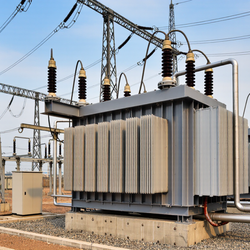
Substation Transformers: Definition and Role in Power Systems
Substation transformers are large electrical machines that change voltage levels within a power system. They use electromagnetic induction to transfer energy between separate windings. A magnetic core links these windings efficiently. More turns on one winding create higher voltage, while fewer turns create lower voltage. The voltage must match the next stage of the grid. Transmission substations often increase voltage for long-distance delivery. Distribution substations reduce it for homes, offices, and factories. The equipment may use insulating oil or solid insulation. Each design has different cooling and maintenance needs. Safety clearances matter.
Their role extends beyond simple voltage conversion. Transformers help control losses, stabilize power delivery, and connect transmission lines with local feeders. Tap changers adjust voltage when demand changes during the day. Protective relays detect faults, while temperature sensors reveal excessive heating. During an inspection, technicians may check oil condition, bushings, grounding connections, and unusual vibration. Small warning signs can become costly failures. No transformer operates perfectly. Energy is lost as heat, and aging insulation can weaken unexpectedly. A carefully planned maintenance schedule reduces risk, but it cannot remove uncertainty. Engineers must still question load forecasts, weather exposure, and cooling performance. A quiet transformer is reassuring, not conclusive. Regular testing provides stronger evidence.
Main Components and Internal Structure
Substation transformers change high-voltage electricity into safer levels for transmission or distribution. Their internal structure is designed for controlled energy transfer, cooling, and fault protection. The magnetic core, built from thin steel sheets, guides magnetic flux while reducing energy losses. Copper or aluminum windings surround the core in carefully spaced layers. One winding receives incoming power, and the other delivers adjusted voltage through electromagnetic induction.
Inside the main tank, insulating oil surrounds the windings and removes heat. It also strengthens electrical insulation between energized parts. Bushings carry conductors safely through the tank wall. A tap changer adjusts the winding ratio when system voltage changes. Depending on the design, radiators, fans, or pumps release heat from the oil. Protection devices monitor pressure, temperature, gas formation, and oil level. In practical inspections, small leaks around seals deserve attention. They may look harmless, but they can reduce insulation reliability over time.
Tips: Keep cooling paths clean and inspect oil condition regularly. Check bushing surfaces for cracks, dust, or unusual marks. A simplified diagram can mislead, because each transformer uses different winding layouts and protection arrangements. Field measurements should guide maintenance decisions, not appearance alone. Even experienced technicians can overlook slow temperature changes.
What Are Substation Transformers and How Do They Work?
Common Nominal Voltage Classes Used in Substations
A substation transformer transfers electrical energy between voltage levels through electromagnetic induction. The high-voltage and low-voltage windings are magnetically coupled through a laminated steel core while remaining electrically isolated.
The chart shows commonly used nominal system-voltage classes found in transmission and distribution substations. Actual transformer nameplate ratings, tap ranges, insulation levels, and applications vary according to the power system design.
- Core: Provides a low-reluctance path for magnetic flux.
- Windings: Transfer energy between the high-voltage, low-voltage, and sometimes tertiary circuits.
- Transformer tank and insulating fluid: Provide mechanical protection, electrical insulation, and heat transfer.
- Bushings: Carry conductors safely through the grounded tank wall.
- Tap changer: Adjusts the turns ratio to regulate the output voltage.
- Cooling equipment: Radiators, fans, or pumps remove heat produced by winding and core losses.
- Protection devices: Pressure-relief equipment, temperature indicators, and gas or oil monitoring help detect abnormal conditions.
How Voltage Is Transformed Step by Step
A substation transformer changes voltage through electromagnetic induction. Power arrives at high voltage, often hundreds of kilovolts, to reduce transmission losses over long distances. Inside the transformer, alternating current enters the primary winding and creates a changing magnetic field in the steel core. That field induces voltage in the secondary winding.
The voltage ratio follows the turns ratio. A winding with fewer turns produces lower voltage. For example, a 230 kV supply may be reduced to 69 kV for regional transmission, then lowered again to 13.8 kV near local distribution networks.
The process is controlled, not instantaneous. Tap changers adjust winding connections when demand changes, helping maintain a stable output. Small changes matter.
Cooling systems remove heat from the core and windings. Protective relays, bushings, oil systems, and circuit breakers support safe operation. The U.S. Energy Information Administration reports that transmission and distribution losses commonly account for roughly 5% of delivered electricity, showing why efficient voltage management matters.
A 2024 U.S. Department of Energy analysis estimated that stronger transformer efficiency standards could save about 3.6 quadrillion British thermal units over 30 years. That figure covers distribution transformers, but the lesson applies across the grid.
The ideal ratio is not the whole story. Real networks are messier. Load growth, harmonics, aging insulation, and weather can alter performance. Engineers therefore monitor temperature, dissolved gases, voltage, and vibration before deciding whether a transformer needs maintenance or replacement.
Types of Substation Transformers and Their Applications
Substation Transformers: Types and Applications
Substation transformers change voltage levels so electricity can travel efficiently and safely. Step-down transformers reduce transmission voltage for regional distribution networks. Their large steel tanks often stand behind fences, with cooling radiators and porcelain bushings visible from a distance. Step-up transformers serve generating stations, raising voltage before power enters long transmission lines. Higher voltage reduces current and limits energy loss across conductors.
Autotransformers use one continuous winding and suit systems with similar voltage levels. They are smaller and often more efficient, but their electrical isolation is limited. Three-winding transformers connect transmission, distribution, and auxiliary circuits within one substation. Grounding transformers create a neutral point and help control fault currents. Phase-shifting transformers adjust power flow between network paths. This function becomes valuable when one corridor carries heavy demand.
Transformer selection depends on load size, voltage ratio, short-circuit strength, cooling conditions, and maintenance access. Oil-immersed units handle high power and outdoor service effectively. Dry-type transformers fit indoor facilities where fire risk and ventilation require closer control. Protection systems monitor temperature, gas formation, oil level, and winding faults. Field engineers also inspect seals, bushings, and grounding connections during scheduled outages. In practice, categories can overlap, and a standard choice may fail under unusual harmonics or seasonal loads. That is where careful measurements matter.
What Are Substation Transformers and How Do They Work? - Types of Substation Transformers and Their Applications
| Transformer Type | Primary Function | Typical Voltage Role | Cooling Method | Typical Rating or Range | Common Applications | Key Characteristics |
|---|---|---|---|---|---|---|
| Power Transformer | Transfers bulk electrical power between transmission and sub-transmission networks. | Usually steps high transmission voltage down to a lower transmission or sub-transmission voltage. | Mineral-oil immersed with natural or forced oil and air circulation; large units may use directed oil flow. | Commonly tens to several hundred MVA, depending on the grid requirement. | Transmission substations, grid interconnections, and major generation evacuation points. | High efficiency, large physical size, conservator or sealed-tank construction, and on-load tap-changing options. |
| Distribution Transformer | Reduces medium voltage to the low voltage used by homes, commercial buildings, and small industrial loads. | Typically steps medium-voltage feeder levels down to low-voltage utilization levels. | Oil immersed or dry type; natural cooling is common. | Usually from a few dozen kVA to several MVA. | Utility distribution feeders, residential areas, commercial facilities, and light industry. | Designed for continuous service and often optimized for low no-load losses because it remains energized for long periods. |
| Step-Up Transformer | Raises voltage while reducing current for efficient long-distance transmission. | Converts generator or lower-voltage power to a higher transmission voltage. | Oil immersed for medium and large ratings; dry type may be used for smaller indoor installations. | From small industrial ratings to several hundred MVA in generating-station service. | Power plants, renewable-energy collector systems, and transmission connection substations. | Improves transmission efficiency by lowering current and therefore reducing resistive line losses. |
| Step-Down Transformer | Lowers voltage to a level suitable for distribution, equipment, or end users. | Converts transmission or medium voltage to a lower sub-transmission, distribution, or utilization voltage. | Oil immersed or dry type, selected according to rating, location, and fire-safety requirements. | Ranges from control and equipment transformers to large substation units. | Distribution substations, industrial plants, commercial buildings, and infrastructure facilities. | Provides the voltage level required by downstream networks while maintaining electrical isolation. |
| Autotransformer | Changes voltage through a winding with a shared electrical portion between the input and output circuits. | Used where the input and output voltages are relatively close. | Usually oil immersed with natural or forced cooling for substation applications. | Often used for high-capacity interconnections between nearby voltage levels. | Transmission interties, voltage regulation, and large industrial power systems. | Smaller, lighter, and generally more efficient than a two-winding transformer of similar capacity, but it does not provide full galvanic isolation. |
| Two-Winding Transformer | Transfers energy between two electrically separate windings. | Can perform either step-up or step-down voltage conversion. | Oil immersed or dry type, depending on size and installation environment. | Available across a broad range from small kVA units to large MVA substation transformers. | General-purpose substations, industrial distribution, and utility networks. | Provides galvanic isolation and flexible voltage ratios with separate primary and secondary windings. |
| Three-Winding Transformer | Connects three voltage levels or supplies multiple circuits from one magnetic core assembly. | May connect transmission, sub-transmission, and medium-voltage systems simultaneously. | Commonly oil immersed with radiators and auxiliary cooling equipment for larger ratings. | Typically used for medium- to high-capacity substation installations. | Grid substations, industrial complexes, and substations supplying multiple voltage buses. | Can reduce equipment count and footprint, but requires careful impedance and load-flow design. |
| Oil-Immersed Transformer | Uses insulating liquid for electrical insulation and heat transfer. | Suitable for medium- and high-voltage conversion at substantial power levels. | Oil circulation may be natural or assisted by pumps; heat is released through radiators or coolers. | Common from distribution ratings to several hundred MVA. | Outdoor substations, transmission networks, generation plants, and large industrial sites. | High thermal capacity and compact design; requires fire protection, leak control, and liquid condition monitoring. |
| Dry-Type Transformer | Uses air and solid insulation instead of liquid insulation and cooling. | Primarily used for medium-voltage to low-voltage conversion and selected medium-power substation duties. | Natural air cooling or forced-air cooling. | Commonly used from small kVA ratings to several MVA, with larger designs available for special applications. | Indoor substations, buildings, tunnels, hospitals, data facilities, and areas with strict liquid-fire restrictions. | Lower leakage risk and simplified installation; requires adequate ventilation and careful control of dust and moisture. |
| Grounding Transformer | Creates a neutral point or provides a controlled path for zero-sequence current. | Used on systems that lack a directly grounded neutral. | Oil immersed or dry type, depending on the installation and fault-duty requirements. | Usually rated for short-duration fault duty rather than continuous transfer of full system load. | Medium-voltage substations, renewable-energy collector systems, and isolated or delta-connected networks. | Improves earth-fault detection and protection coordination; may be paired with a neutral grounding resistor. |
| Rectifier Transformer | Supplies a controlled AC voltage to a rectifier that converts AC power into DC power. | Adapts the utility voltage and phase arrangement to the requirements of the rectifier system. | Usually oil immersed with cooling designed for harmonic and load heating. | Rating depends on the DC output, duty cycle, harmonic content, and rectifier configuration. | Industrial electrolysis, traction power, metal processing, battery charging, and high-power DC systems. | Designed to withstand harmonic currents, commutation effects, and frequent or continuous high-load operation. |
| Converter Transformer | Interfaces an AC network with power-electronic converters used to control or convert electrical power. | Matches grid voltage and insulation requirements to converter valves or semiconductor equipment. | Typically oil immersed with specialized cooling for high continuous loading and harmonic losses. | Large ratings are common in high-power transmission and industrial conversion systems. | High-voltage direct-current links, flexible AC transmission, and large industrial converters. | Requires advanced insulation coordination, harmonic design, leakage-reactance control, and cooling analysis. |
Safety, Cooling, Maintenance, and Operational Challenges
What Are Substation Transformers and How Do They Work?
Substation transformers raise or lower voltage between transmission and distribution networks. Their steel cores guide magnetic flux, while copper windings transfer energy without direct electrical contact. The process is reliable, but not effortless. CIGRE’s transformer reliability survey examined 964 failure records and identified windings, insulation, and tap changers among recurring problem areas. Small defects can become costly outages.
Safety begins with isolation, grounding, and verified absence of voltage. Operators also monitor oil temperature, winding temperature, pressure, and dissolved gases. According to IEEE guidance, dissolved-gas analysis can reveal overheating, arcing, and insulation deterioration before visible damage appears.
Cooling systems use radiators, fans, or pumps to remove heat. A blocked radiator is not a minor detail. It can reduce loading capability quickly.
Maintenance needs evidence, not assumptions. Infrared inspections can find hot connections, while oil tests track moisture and insulation aging. The U.S. Energy Information Administration reports that transmission and distribution losses commonly represent about 5% of electricity delivered, showing how small inefficiencies accumulate across networks. Operational challenges include sudden load changes, harmonics from electronic equipment, lightning, and extreme weather. CIGRE data also reminds engineers that failure rates vary by age, design, and service conditions. A fixed calendar is convenient, but sometimes incomplete. Field observations should challenge the maintenance plan.
English
Česká republika
Deutsch
Dutch
Polska